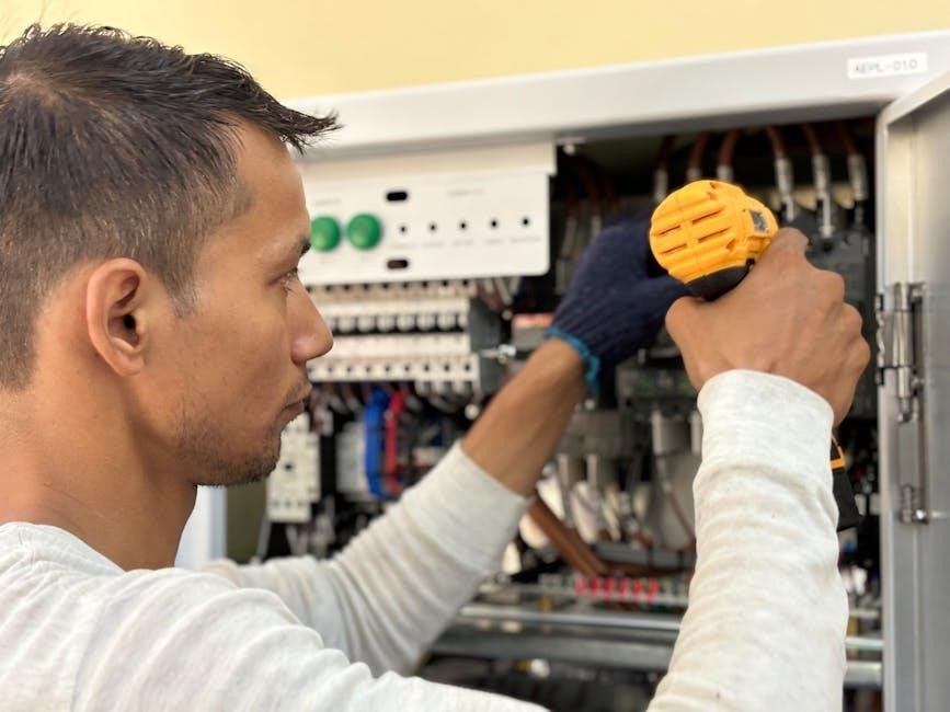
Welcome to the Veeder-Root TLS-350 Troubleshooting Manual, your comprehensive guide for resolving common issues with the TLS-350 and TLS-350R systems. This manual provides detailed instructions and solutions to ensure optimal system performance and safety.
1.1 Overview of the TLS-350 System
The Veeder-Root TLS-350 is a advanced automatic tank gauging system designed for monitoring fuel storage tanks and piping. It includes components like the ECPU board, sensors, and communication modules. The system is part of the TLS-3XX series, offering precise leak detection, pressure monitoring, and inventory management. It supports integration with Point-of-Sale (POS) applications and is compatible with Volumetric Line Leak Detector (VLLD) for enhanced safety. The TLS-350 ensures compliance with environmental regulations and is widely used in retail fueling and industrial settings.
1.2 Importance of Proper Troubleshooting
Proper troubleshooting of the Veeder-Root TLS-350 system is crucial for preventing equipment damage, ensuring compliance, and maintaining safety. Incorrect procedures can lead to system failures, environmental hazards, or even legal penalties. Regular diagnostics and adherence to manufacturer guidelines help prevent minor issues from escalating. This manual provides step-by-step solutions to address common problems, ensuring operators can resolve issues efficiently and safely, minimizing downtime and protecting both the system and the environment from potential risks.

Common Issues and Solutions
This section addresses frequent TLS-350 system issues, such as alarm troubleshooting, pressure integrity test failures, and filter basket leaks. It provides practical solutions to restore functionality and prevent downtime.
2.1 Alarm Troubleshooting Summary
Alarms on the TLS-350 system indicate potential issues requiring immediate attention. Common causes include pressure sensor malfunctions, communication errors, or leak detections. This section provides a concise summary of alarm conditions, diagnostic steps, and corrective actions. Refer to the detailed troubleshooting procedures for resolving specific alarm codes. Regular system checks and calibrations can help prevent alarms and ensure reliable operation. Always consult the manual for precise instructions to address alarms effectively and maintain system integrity.
2.2 Pressure Integrity Test Failures
Pressure integrity test failures in the TLS-350 system often indicate issues with the filter basket, sensor connections, or system calibration. Start by inspecting the filter basket for leaks or blockages and ensure all screws are tightened properly. Verify the integrity of the pressure sensor and its wiring connections. If issues persist, recalibrate the system according to the manual’s instructions. Regular maintenance and checks can prevent such failures, ensuring accurate leak detection and system reliability. Always refer to the manual for detailed diagnostic steps.
2.3 Filter Basket Maintenance and Leaks
Regular maintenance of the filter basket is crucial to prevent leaks and ensure optimal system performance. Inspect the basket for signs of wear or damage. Tighten the four retaining screws firmly and check the o-ring for integrity. Replace the o-ring if damaged or worn. After maintenance, rerun the Pressure Integrity Test to confirm the system’s functionality. Addressing leaks promptly prevents false alarms and maintains accurate leak detection. Always follow the manual’s guidelines for proper maintenance procedures.

System Components and Replacement
This section covers the replacement of critical TLS-350 components, including the ECPU board and software modules. Always use authorized service representatives for proper installation and functionality. Refer to specific manuals for detailed instructions to ensure system integrity and performance. Proper replacement procedures are essential for maintaining accurate leak detection and overall system reliability.
3.1 ECPU Board Replacement Instructions

- Power down the system before starting the replacement to ensure safety and prevent damage.
- Remove the old ECPU board by disconnecting all cables and screws. Handle components with care to avoid static discharge.
- Install the new ECPU board, securing it with screws and reconnecting all cables as per the manual.
- Replace the software chips (U19, U22, U25) using a chip removal tool to avoid damage.
- Restart the system and run diagnostics to ensure proper functionality.
- Consult the manual for specific instructions and safety precautions to avoid system malfunctions.
Always use authorized service representatives for ECPU board replacement to guarantee system reliability and performance.
3.2 Software Modules and Memory Upgrades
This section provides instructions for upgrading or replacing software modules and memory in the Veeder-Root TLS-350 system. Ensure compatibility with your system by referencing the manual. To upgrade, remove the old software chips (U19, U22, U25) using a chip removal tool to prevent damage. Install the new chips securely and restart the system. Always follow the manual’s guidelines for proper installation and testing; Contact an authorized service representative for assistance if needed.

Preventive Maintenance and Safety
Regular system checks ensure optimal performance and safety. Perform intrinsic safety checks and calibrations as outlined in the manual to prevent hazards and maintain compliance with regulations.

4.1 Regular System Checks and Calibrations
Regular system checks are crucial for maintaining optimal performance and safety. Inspect probe and sensor wiring, ensuring compliance with Veeder-Root requirements. Check the filter basket for leaks, tighten screws, and replace the o-ring if necessary. Run pressure integrity tests and verify sensor connections. Adhere to the manual’s guidelines for calibration schedules and procedures. Replace worn components promptly to prevent failures. These routine tasks ensure accurate monitoring and compliance with safety standards, minimizing downtime and potential hazards.
4.2 Intrinsic Safety Check Procedures
Intrinsic safety checks are essential to prevent explosions in hazardous environments. Verify probe and sensor wiring meets Veeder-Root standards, referencing manual P/N 576013-879. Inspect all connections and conduits for integrity. Ensure system components are properly grounded and free from damage. Follow manual warnings to avoid risks of explosion or injury. If the system fails the intrinsic safety check, consult the troubleshooting guide or contact an authorized service representative for assistance. Always prioritize safety when performing these critical checks.

Advanced Troubleshooting Techniques
Advanced methods focus on verifying probe and sensor wiring, ensuring proper system configurations, and addressing complex issues. Follow detailed procedures outlined in the manual for optimal results.
5.1 Probe and Sensor Wiring Verification
Proper wiring is critical for accurate measurements. Verify probe and sensor connections, ensuring they meet Veeder-Root specifications. Check for corrosion, damage, or loose connections. Use the manual’s wiring diagrams to confirm configurations. Test continuity and resistance to identify faults. Ensure all conduits and cables comply with intrinsic safety standards. Correct any issues promptly to prevent data inaccuracies and system malfunctions. Refer to the manual for detailed procedures and safety guidelines.
5.2 DIM Card Installation and Configuration
For proper functionality, install and configure the DIM card according to the TLS-350R Point-of-Sale (POS) Application Guide. Ensure the system is powered down before installation. Refer to the DIM card manual for specific instructions. After installation, test communication between the DIM card and the console. Verify configuration settings match your application requirements. Contact technical support if issues arise during setup. Proper installation ensures seamless integration and optimal system performance.

TLS-350R Specific Troubleshooting
This section addresses specific issues unique to the TLS-350R model, including VLLD malfunctions and POS integration challenges, ensuring tailored troubleshooting for advanced system configurations.
6.1 Volumetric Line Leak Detector (VLLD) Issues
The VLLD in the TLS-350R may experience inaccuracies in leak detection or fail to trigger alarms. Common causes include sensor misalignment, debris buildup, or software glitches. To troubleshoot, inspect the sensor wiring for damage and ensure proper calibration. Verify that the filter basket is clean and free of leaks. If issues persist, refer to the TLS-350R POS Application Guide for detailed diagnostic procedures. Contact technical support if system errors remain unresolved after these steps.
6.2 POS Application Setup and Integration
For the TLS-350R, ensure the POS application is correctly configured to communicate with the system. Verify proper installation of the DIM card and refer to the TLS-350R POS Application Guide for setup instructions; Check all wiring connections and ensure software versions are compatible. If integration issues arise, recalibrate the system and confirm settings match the application requirements. Persistent problems may require consulting the TLS Systems Technical Support or an authorized service representative for assistance.

Contacting Technical Support
For further assistance, contact TLS Systems Technical Support at 800-323-1799 or consult an authorized Veeder-Root service representative for professional help and guidance.
7.1 Authorized Service Representative Assistance
For expert assistance, contact an authorized Veeder-Root service representative. They provide professional troubleshooting, repairs, and system calibrations, ensuring compliance with safety standards. Representatives are trained to handle complex issues, offering personalized support for TLS-350 and TLS-350R systems. They can also guide you through advanced diagnostics and provide genuine replacement parts. Contact them via phone or email for prompt service, ensuring your system operates efficiently and safely. Their expertise guarantees reliable solutions tailored to your specific needs.
7.2 TLS Systems Technical Support Contact Details
For additional support, contact TLS Systems Technical Support at 800-323-1799. Their team is available to assist with advanced troubleshooting, software updates, and system configurations. You can also reach them via email for inquiries or to schedule a service call. Visit their official website for more contact options and resources. Ensure to have your system details ready for efficient assistance. Their expertise ensures your TLS-350 and TLS-350R systems operate at peak performance. Contact them today for reliable support.
